
EQUIPMENT
From the dynamometer to the control software, all equipment is designed and manufactured by GTDyno. Browse by category below and download datasheets.
Hydraulic water-brake, AC (active, 4-quadrant, regenerative) and eddy-current dynamometers; 0.1–20,000 HP, 200,000 Nm, up to 60,000 rpm.
Our own control & reporting platform TRex (Beckhoff hardware): full automation, PID, continuous limit monitoring and third-party integration.
Throttle, exhaust back-pressure, intake-air flap and gear-shift actuators — precise, repeatable, fully automatic test steps.
Gravimetric fuel/air/oil consumption units, combustion analysis, multi-point temperature/pressure — calibratable, precise measurement.
Temperature, pressure, flow and humidity conditioning for engine water, fuel, oil and intake air — automatic control.
Main and auxiliary frames, vibration isolation, flexible couplings, connection adapters and quick-docking plates.
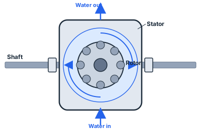
Hydraulic water-brake (absorbing-only): ideal for long-duration endurance, low maintenance, 30–40 year life.
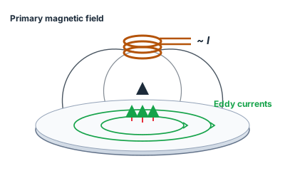
Eddy-current (absorbing-only): fast, precise load change, mid-segment.
AC dynamometer (active, 4-quadrant): operates in all four quadrants — in both clockwise (CW) and counter-clockwise (CCW) rotation it can drive (motoring) and brake (absorbing). Regenerative; the most precise control.
The right dynamometer type is determined by test duration, load profile, speed range and budget. Since we manufacture all three main types under our own design, we recommend the most suitable one impartially.
We manufacture every device used in the test facility with our own engineering: gravimetric consumption measurement units, combustion analysis, conditioners, actuators, mechanical frames and coupling elements.
TRex is the brain of the test cell and belongs entirely to us. Running on Beckhoff industrial hardware, the platform manages dynamometer load control, engine throttle control, conditioning units and measuring instruments from a single interface. Operating modes such as constant-speed torque control, constant-torque speed control and constant throttle-position control can be switched seamlessly during the test.
The platform performs continuous limit monitoring: when temperature, pressure, speed, torque or vibration values exceed defined limits it first warns, then if necessary brings the engine to idle or stops it safely. All test data is recorded with time stamps; tests run at different times are reported in the same format and become comparable.
Because all source code of the software belongs to us, project-specific functions can be written. Full integration with third-party systems — emission analysers, combustion analysis hardware, HIL and development sub-systems — is achieved via modern communication protocols. For budget-limited applications, economical control units with a potentiometer and speed/torque/power indication are offered.
For fully automatic test steps to run, the engine and its peripherals must be driven precisely. The engine throttle robot sets the throttle position with repeatable accuracy, so the same test step is applied identically every time. Exhaust back-pressure actuators and intake-air flaps control the flow conditions the engine experiences.
In transmission testing, gear-shift and clutch actuators repeatably imitate driver behaviour. On the dynamometer side, load control actuators precisely adjust the water flow of the hydraulic dynamometer and therefore the absorbed power. General-purpose actuators provide flexibility for project-specific mechanisms.
A dynamometer is a machine that absorbs the power produced by the unit under test in a controlled manner while measuring torque and speed. The housing sits on a pedestal so that it can swing freely on bearings; as the rotor turns, the reaction moment transferred to the housing is transmitted through a lever arm to a load cell. The force read from the load cell multiplied by the lever length gives torque; torque multiplied by angular speed gives power. This principle is common to hydraulic, eddy-current and AC dynamometers; the difference lies in the physical means by which power is absorbed.
In a hydraulic (water-brake) dynamometer, power is converted into heat through the turbulence of water flow between rotor and stator and removed by the cooling water circuit. Load is controlled by adjusting water flow and thus fill level. Because this design can absorb very high power for long periods without trouble it is indispensable for durability testing; it has few wearing parts, hence low maintenance cost and very long life.
In an eddy-current dynamometer the rotor turns within a magnetic field and the induced eddy currents convert power into heat. Load can be adjusted very rapidly by changing the coil current, which is why it is preferred in cycle tests requiring fast load changes. In an AC active dynamometer the electrical machine works as both generator and motor: during braking the energy produced is returned to the grid through the drive, and when required it drives the unit under test, performing motoring. Four-quadrant operation expresses exactly this capability.
To maintain measurement accuracy the load cell chain is calibrated periodically. Calibration is performed with known weights via the calibration arm and supported by an automatic calibration function. Speed measurement uses an encoder or dual hall-effect sensors; dual sensors also allow direction of rotation to be detected. Precise shaft alignment is critical both for measurement accuracy and for coupling and bearing life.