
TEST SYSTEMS
Turnkey test systems with single-source responsibility by GT: from engines to gearboxes, electric motors to turbines — delivered ready to run.
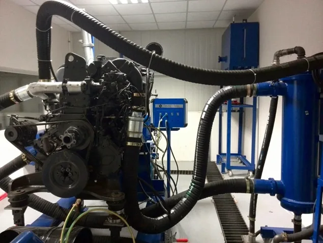
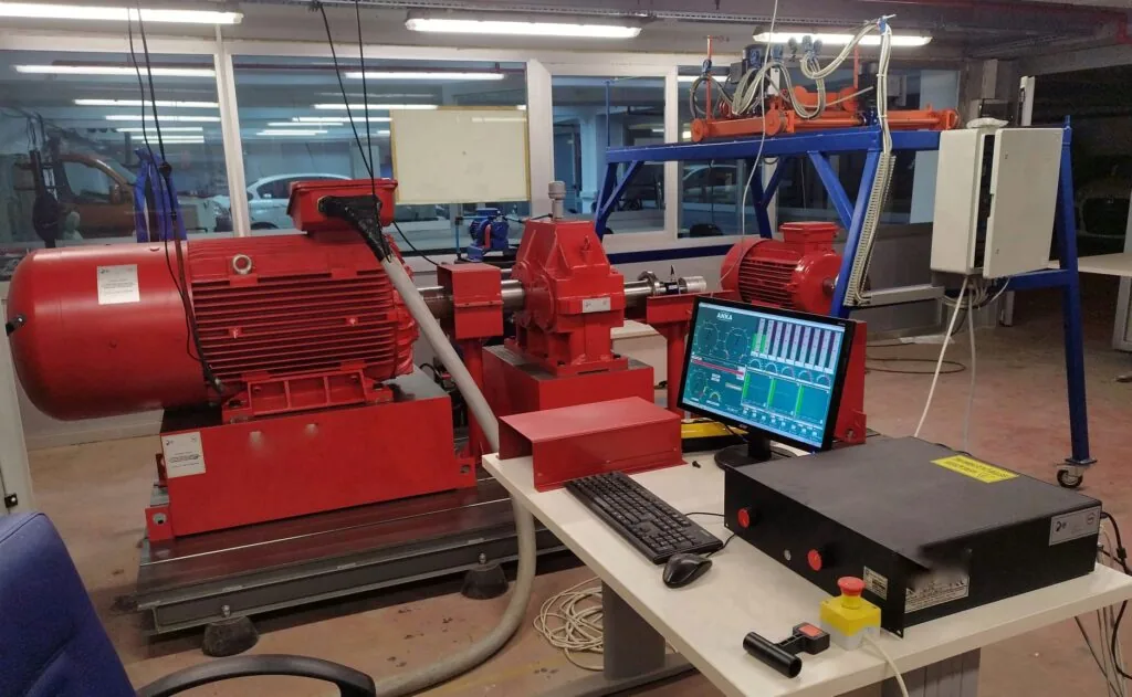
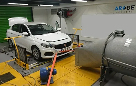
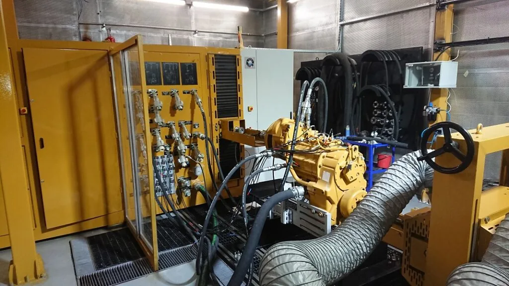
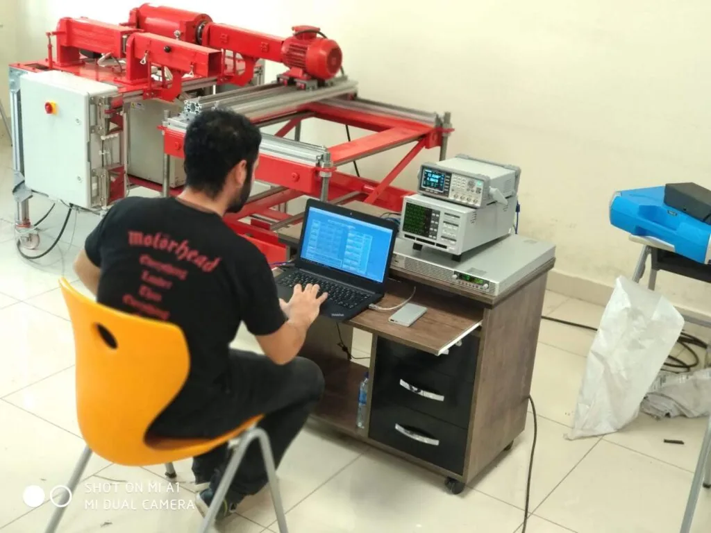
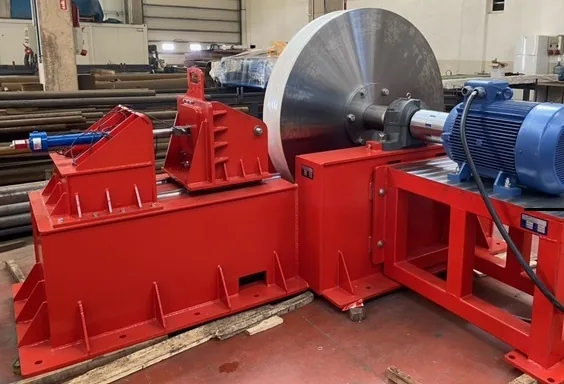
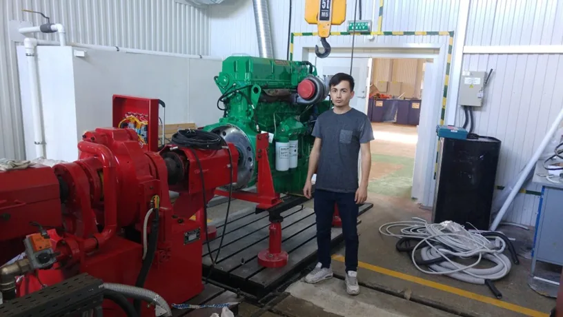
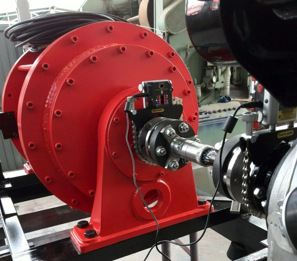
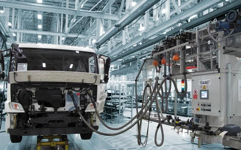
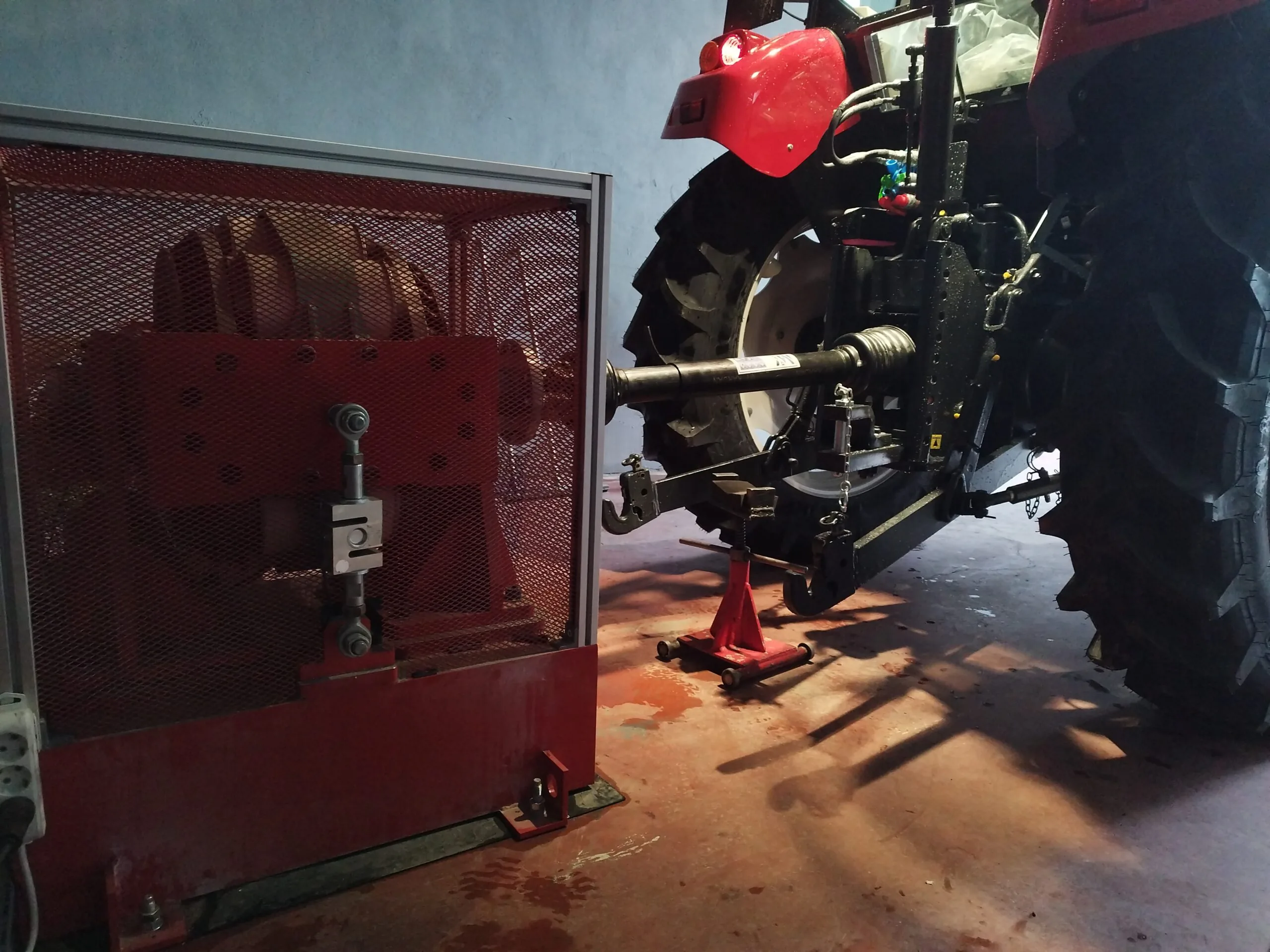
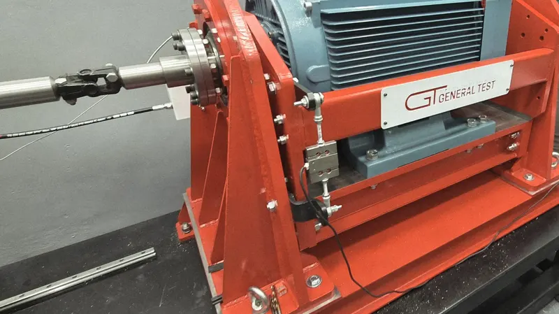
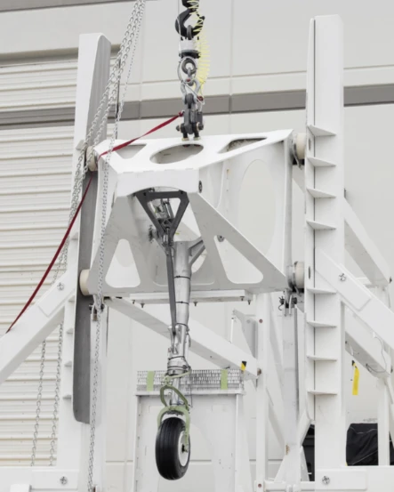
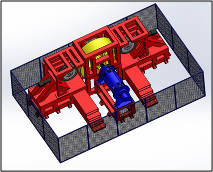
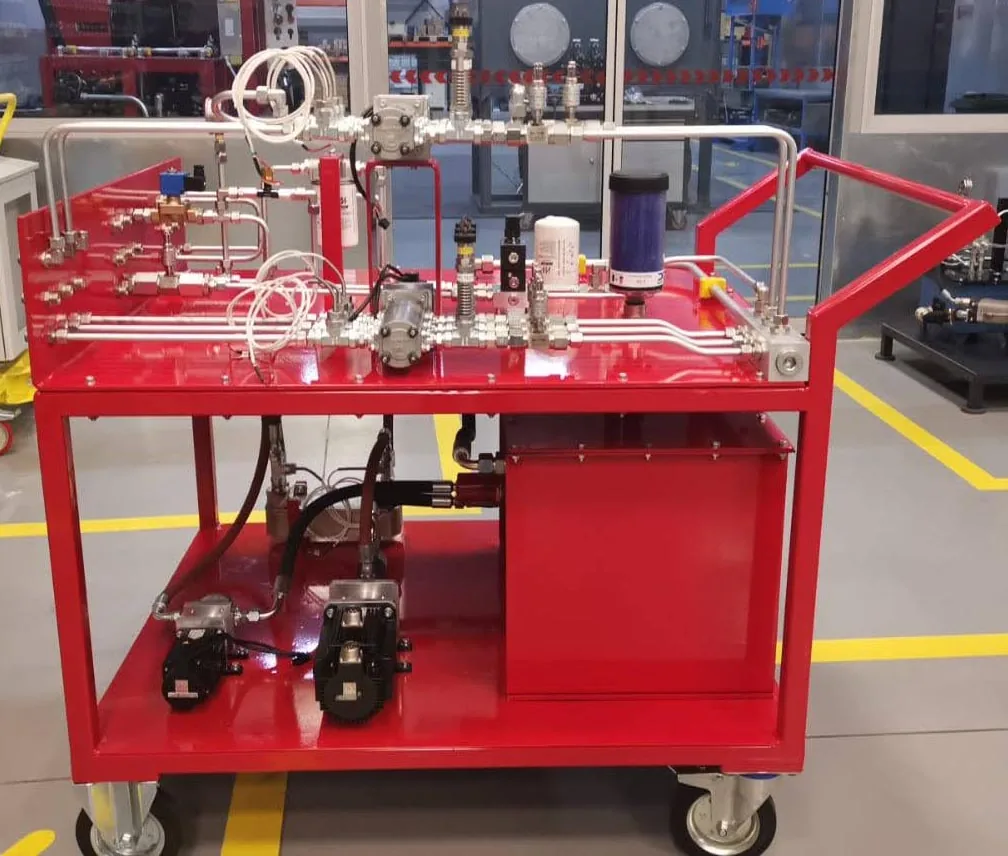
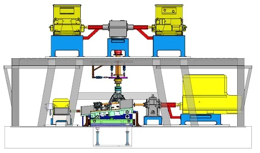
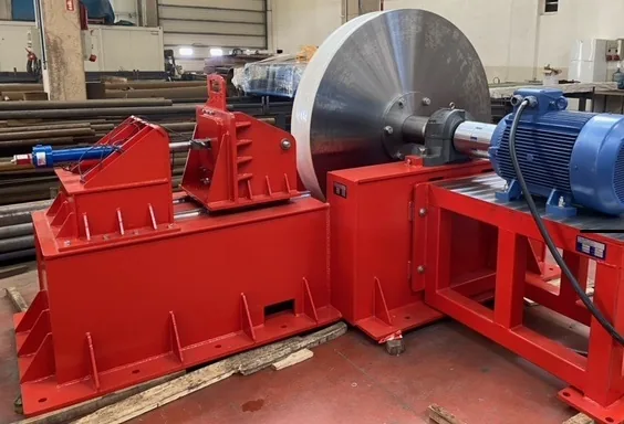
We build turnkey test systems for combustion engines running on diesel, gasoline, LPG, CNG and alternative fuels. The engine test dynamometer, control unit, conditioning and measurement equipment are all our own design and manufacture. The test cell runs, loads and stresses the engine as close as possible to real road conditions, and results are reported under traceable, repeatable laboratory conditions.
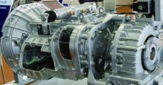
In transmission test dynamometer and powertrain test systems, manual and automatic gearboxes, transaxles, differentials, axles and gear boxes are tested under full load. Depending on the application a hydraulic (water-brake), eddy-current or AC active dynamometer is selected; where required a dual architecture drives the input (motoring) and brakes the output.
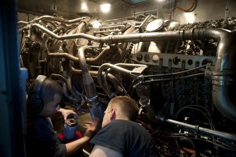
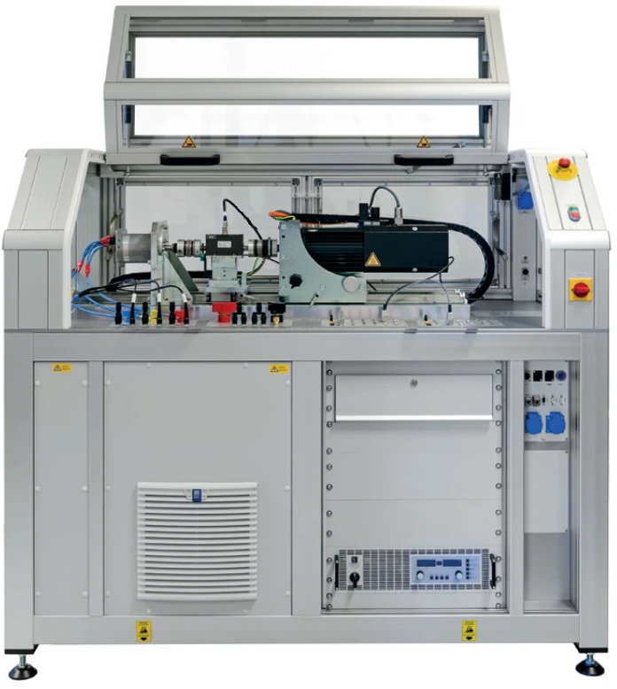
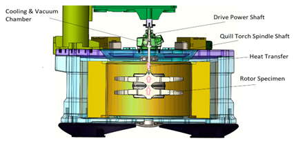
We provide high-speed test solutions for electrification and aerospace applications. E-motor test systems achieve four-quadrant operation with regenerative AC dynamometers; for turbine, turboprop and turboshaft engines high-speed capability up to 60,000 rpm is offered.
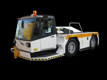
For applications where the complete vehicle must be tested we provide chassis dynamometer and towing dynamometer solutions. Tests are carried out in the laboratory, as close as possible to road conditions, with traceable reports.
Setting up an engine test cell or transmission test system is not merely dynamometer supply. The process begins by clarifying which tests the customer will actually perform and to which standards. The power, torque and speed range of the unit under test; the duration and repetition of the test; the physical quantities to be measured and the reporting expectation are all defined. This analysis ensures the correct dynamometer type is chosen — hydraulic water-brake, eddy-current or AC active; a wrong choice permanently raises both investment cost and operating expense.
After the needs analysis the test cell layout is produced. The engine carrying arrangement, dynamometer pedestal, concrete main block and vibration isolation; exhaust extraction, fresh air intake, fire detection and cooling water circuit are planned at this stage. Utilities around the cell — ventilation, lighting, chilled water — are designed to be managed from the same control platform as the test system. The operator thus runs both the test and the facility from a single interface, which improves both occupational safety and repeatability.
After manufacturing and integration the system is brought into operation on site, parameterized to the customer’s test requirement and operator training is delivered. During commissioning the torque and speed measurement chain is calibrated and results are certified. The facility is not left alone after delivery either: with periodic calibration, preventive maintenance and capacity upgrades where needed, the test cell retains its measurement reliability throughout its life.
The value of a test system equals the reliability of the data it produces. In GT test systems torque is typically measured with 0.2% accuracy and speed with ±1 rpm accuracy, and the measurement chain has automatic calibration capability. Quantities such as temperature, pressure, flow and humidity are measured with sensors calibrated on the engine, so the figure in the report genuinely represents the physical value the engine experiences.
Running tests with fully automatic steps makes results independent of the operator and of seasonal ambient conditions. Ambient conditions are either directly controlled or normalized through correction-factor calculation. Two tests performed six months apart therefore remain comparable, and product development decisions rest on a reliable basis.
Reports are produced in accordance with international test standards; calibration certificates are attached and visual graphics, processed numerical data and raw data are presented together. Reports are editable and can be added directly to the customer’s own quality documentation. For emission testing, measurement infrastructure compliant with EURO and EPA regulations is established; in durability testing the engine is run continuously under full load for 1,000, 2,000, 5,000 hours or longer to verify life and localization.
Which dynamometer should I buy? The decision depends on test duration and load profile. For long-duration full-load endurance testing the hydraulic (water-brake) dynamometer is most suitable: it absorbs high power for long periods without trouble, has low maintenance cost and with correct maintenance serves 30–40 years. For rapid load changes and mid power range, eddy-current is suitable. Where motoring is required — that is, the dynamometer must drive the unit under test — an AC active dynamometer is essential; it also lowers operating cost by returning braking energy to the grid, though initial investment and maintenance costs are higher.
Can I refurbish my existing test cell or should I build new? In most cases the existing mechanical infrastructure (concrete block, frame, dynamometer body) is sound and only the control unit and measurement chain have become outdated. Modernization is then far more economical than new investment: adding a modern control unit, calibratable measurement chain and automatic reporting to the old dynamometer brings the cell up to date. Before deciding, an analysis of the existing facility is performed and an efficiency improvement report is prepared.
How long does a test cell installation take? The duration varies with the scope of the facility and construction requirements. There is a significant difference between a standard engine test cell installed in an existing building and a complete new test facility. The project plan is produced during the needs analysis phase; manufacturing, shipment, site integration, commissioning and training steps are all scheduled. The single responsible contractor model shortens the schedule by eliminating waiting times between suppliers.
Will my test reports be internationally accepted? Our test systems are equipped with calibratable and accreditable measurement equipment, and reports are produced in a format compliant with international test standards with calibration certificates attached. Our customers can therefore create their own certified test reports in their own laboratories, removing dependency on external laboratories and the associated loss of time.
Can the system be expanded later? Yes. Our TRex control platform is modular; torque and speed measurement channels can be expanded up to 256 channels, and new measuring instruments and conditioning units can be integrated later. Because the software source code belongs to us, project-specific functions can also be written later; there is no third-party approval or licence restriction.
A test cell consists of more than a dynamometer and an engine. Safe exhaust extraction, fresh air supply, cell temperature control, cooling water generation and distribution, fuel supply and return lines, fire detection and suppression, and the emergency stop chain are auxiliary systems that must be designed together for the test to run safely and without interruption.
Managing these systems from the same interface as the test control platform is a significant advantage. Ventilation starts before the test begins and cooling water temperature is brought to the target value; at the end of the test the systems are shut down in a controlled manner. When a limit is exceeded, not only the engine but the related auxiliary system is also brought to a safe state. The operator sees both test and facility status on a single screen.
For personnel safety the test cell and control room are separated; observation is via bullet-proof glass or a camera system. A door interlock prevents the cell door being opened while the engine runs. Protective guards for rotating parts and a safety cage around the coupling and shaft area are standard. These measures are the concrete expression of our ISO 45001 occupational health and safety approach.